Model View Controllers
Contents
- Overview
- Model Diagram Synchronization
- Models
- Diagrams
- Mappings
- Mapping Patterns
- Equality Pattern
- Containment Pattern
- Model Diagram Implementation
- A Simple Database
Synchronizer
Overview
A typical example of model synchronization occurs when a model is visualized as a diagram. There are many software tools available that provide access to a model via a diagram. You can create an instance of the model by interacting with the diagram. Sometimes, the tool also supports interacting with the model instance via other routes: via property editors or a scripting language. Where the instance can be modified in this way, it is important that the diagram view is updated to be consistent. Consistency update may be automatic or may be explicitly invoked via a refresh.This section defines a modelling language, a diagram model and shows how the two can be synchronized by modelling a mapping between them. It turns out that the mappings conform to a small number of patterns that can be reused to create model synchronizers.
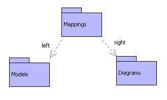
The diagram above provides an overview of the synchronization architecture for the example. The left-hand package defines a simple data modelling language consisting of the usualy components: packages; classes; attributes and inheritance. The right-hand package defines a simple model for diagrams including: diagrams; nodes; edges and display elements. A diagram display element has a position and may be either a box (container of display elements) or a text string.
The package in the centre contains a definition of mappings that are used to synchronize models and diagrams. The idea is that a mapping connects instances from the left with their corresponding instances on the right such that when a change occurs on one side, the change can be reflected in the corresponding element on the other side.
Model-Diagram Synchronization
Here's an example. Support there is a class named C in a package. Then
there should be a diagram with a node for C. The node for C contains a
box which in turn contains a text item whose text is the string ``C''.
Mappings are used to:- connect the package to the diagram
- connect the class to the node
- connect the class name to the text item
Notice that in both the scenarios given above, it was not necessary for the model element to know about the diagram element and vice versa. This is an important issue: when model instances are synchronized, the machinery must ensure a separation of concerns. There is no reason why the model should know about the diagram -- to do so would compromise reusability of the model. Similarly, if the diagram elements are directly associated with the model elements then this makes it difficult to use the diagram model in a variety of circumstances (domain specific languages for example).
Models
The following diagram shows a simple data model consisting of packages, classes, attributes and generalizations. This model is representative of many data modelling notations.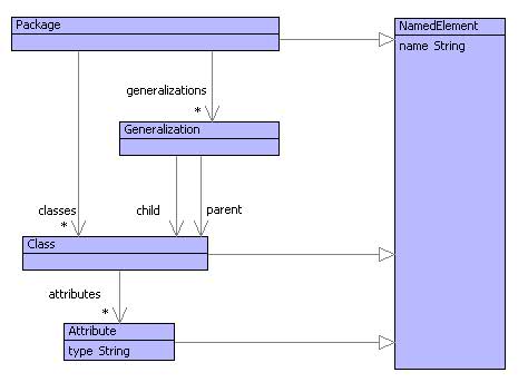
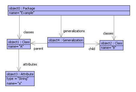
The following diagram shows an example model as it would be seen in a diagram editor. The snapshot shown below is the same model as that shown above:
Diagrams
Diagrams contain nodes with edges between them. Each node has a position on the diagram and contains a collection of displays. A display has a co-ordinate that is relative to its container; it may be a text item or a box (bordered container of display elements). The model for diagrams is shown below: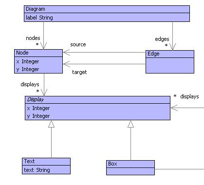
The diagram snapshot of the example model in the previous section is shown below:
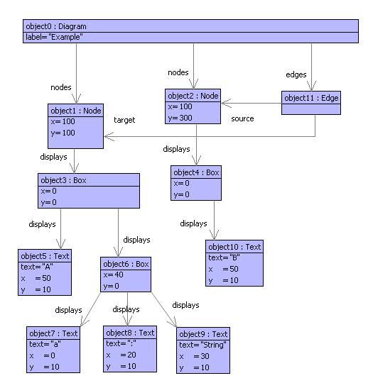
A diagram has a label that is intended to be the same as the name of the corresponding package. Each class is shown as a node and generalizations are shown as edges between class nodes. A class is drawn as a box, with the name as a text item at the top followed by attribute boxes. Each attribute box contains text items for the name, ``:'' and the type of the attribute. Note that in the example, the positions of the nodes and displays are illustrative.
Diagrams know nothing about classes, attributes and generalizations. This is as it should be since we could choose to use the diagram model to display a variety of information including class-models, snapshot-models, CPM networks and decision trees.
Mappings
The following diagram: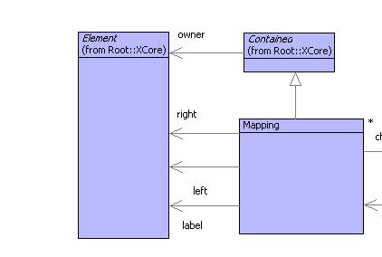
shows a model of mappings that can be used to synchronize a class-model with a diagram. A mapping is a tree structure that link elements from a left-hand model with elements from a right-hand model. Each mapping has a label that can be used to distinguish between different mappings between the same left and right elements.
Mappings sit between the left and right-hand elements in order to record the fact that they should be the same in some sense. As such, a mapping can have intimate knowledge of the left and right-hand model structures. In the case of a class-model and a diagram, mappings can be expected to know that a class has a name and the related diagram node has a text item that is used to display the class name. Neither the class-model or the diagram model know anything about each other, so there is a clear division of concerns: cross-model information is limited to the mapping.
Mappings can be used to relate any elements from the left and right-hand models and a mapping is is a tree structured thing (made up of maplets). It is up to us as modellers to decide how to structure and use the mapping. Each mapping has children that are other mapping components. The idea is that if the left and right elements are composed of children then the mapping will have maplets that appropriately relate those children. For example, a package may be related to a diagram via a mapping composed of maplets that relate the package's classes with the diagram's nodes.
Mappings simply record the associations between left and right-hand elements. There is no requirement for mappings to be used in any particular way. However, it turns out that there are useful patterns of mapping usage, both in terms of how they relate models that are themselves structured using standard patterns.
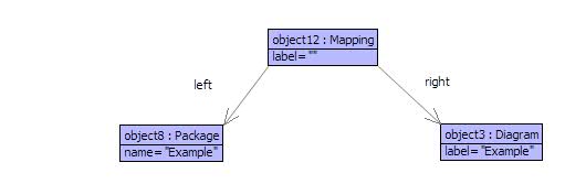
The following figure shows how a package and a diagam are associated using mappings. This is a root mapping and is responsible for synchronizing the package with all its components against the diagram with all its components. The mapping object12 is individually responsible for keeping the name of the package synchronized with the diagram label; it devolves responsibility for the class and generalization synchronization to its child maplets:
The following figure:
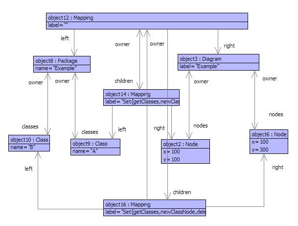
shows the child maplets of the root package/diagram mapping. The root mapping has two children:; object14 and object16 that are responsible for associating classes A and B with their corresponding diagram nodes. In each case the maplets have labels (the detail of which is not shown) that identify them as being class-associating mappings.
It is worth considering how this mapping migh be used as part of a tool. Suppose that the name of the package (object8) is modified, to X. The resulting event causes a synchronization to occur (or the user manually causes a synchronization to occur) which in turn asks the mapping (object12) to synchronize its left and right elements. At this stage, the name at object8 is X whereas the label at objct3 is Example. The mapping object12 detects this inconsistency and modifies the label (causing a change in the GUI). The story would be much the same if the label was changed causing the packag name to be modified.
Now consider what happens if we add a class node to the diagram. Suppose that objects 6, 16 and 10 have yet to be added (i.e. the model contains only class A). The user adds a node to the diagram (object6) and the synchronization is started, as before, at object12.
Part of the synchronization task of object12 is to ensure that, if the diagram has changed, every node has a corresponding class. The mapping object12 can do this because it has access to (and knowledge of) both packages and diagrams. When this check is performed, object12 detects that there is a node (object6) for which there is no child maplet. Therefore, the model and diagram are inconsistent. The remedy is to create a class (object10) and associate it via a new maplet object16 with the diagam node. The story is much the same if a class is added to the model: a new node is added to the diagram and a maplet to the root mapping.
Mapping Patterns
Mappings are used to link left-hand instances to rght-hand instances and mappings are structured into trees of maplets. So far, synchronization has been described in rather hand-wavy terms. This is because, in general, many different synchronization strategies and implementations are possible ranging from those that are implemented by hand (and guided by the mappings) to those that are fully automated.In many circumstances, it is possible to define mapping patterns such that mappings can be applied to instances of left and right models in chunks. Moreover, the pattern chunks can be made to be self manging in terms of synchronization. The next couple of sections show how an analysis of the model-diagram example leads to patterns and then shows how the patterns can be defined in XMF. The following section then gives the full implementation of the model diagram application in terms of the patterns.
Equality Pattern
Consider classes and attributes. They have a feature in common: they both have names. Consider class diagrams and the rendering of classes and attributes. They are each rendered as text items in boxes such that the synchronization ties up the name with the string in the text item.Class and attribute name synchronization is an example of and equality pattern. Where a left-hand item (the name) is defined to be equal to a right-hand item (the string). The difference between the two examples, occurs in terms of how the name/string is accessed, updated and created.
Suppose that an equality synchronization pattern is defined. What are its different modes of operation:
- If a left-hand instance exists but a right-hand instance does not then the maping is being used to genrate the right from the left. It must be possible to creat a new instance of the appopriate right-hand element and link it to the left with a maplet.
- If a left-hand instance changes then we must be able to update the right-hand instance.
- If a right-hand instance exists, but a left-hand instance does not then proceed as for 1 (right to left).
- If a right-hand instance chages then proceed as for 2 (right to left).
@Operation syncEqualLeft(lab,getLeft,setRight,newRight,mapping)
(1)  let left = mapping.left();
         right = mapping.right()
(2)  in @Find(child,mapping.children())
(3)       when child.label() = lab
(4)       do if getLeft(left) <> child.left()
             then
(5)            child.setLeft(getLeft(left));
               child.setRight(getLeft(left));
               setRight(right,getLeft(left))
          end
         else
(6)        let new = newRight(right,getLeft(left)) then
(7)            child = Mapping(lab,getLeft(left),new)
(8)        in mapping.addToChildren(child)
           end
        end
    end
  end
Line (1) extracts the left and right elements from the mapping. Lines (2-3) select a maplet linking the synchronized elements. If this exists then a check is made at (4) to see if the leftt-hand element has changed. If it has changed then the element will be out of sync with the maplet and lines (5-) update the appropriate components thereby synchronizing.
Line (6) occurs when the maplet for the synchronized elements dos not exist. This occurs when the right-hand element is being generated from the left. In this case, a new right-hand element is constructed (6). Imagine class-names being synchronized with text items: the arguments in (6) are the node and the class-name.
Line (7) creates a new maplet (assumed synchronized) and (8) adds the maplet to the parent mapping.
Containment Pattern
Consider packages and classes (similarly classes and attributes) compared with diagrams and nodes (similarly nodes and contained boxes). In both cases one element contains a collection of sub-elements: packages contain classes; diagrams contain nodes. Synchronization of such elements can be captured as a containment pattern with the following modes:- Addition of a new left-hand instance (e.g. a class) causes addition of a corresponding right-hand instance (e.g. a node).
- Deletion of a left-hand instance causes deletion of the corresponding right-hand instance.
- Addition of a right-hand instance (as for 1 but right to left).
- Deletion of a right-hand instance (as for 2 but right-to-left).
@Operation syncSetsLeft(lab,getLeft,newRight,deleteRight,mapping,subSync)
(1) let left = mapping.left();
        right = mapping.right()
(2) in @For x in getLeft(left) do
(3)      @Find(child,mapping.children())
(4)        when child.left() = x
(5)        do subSync(child)
           else
(6)          let y = newRight(mapping,x,right) then
(7)              child = Mapping(lab,x,y)
(8)          in mapping.addToChildren(child);
(9)             subSync(child)
             end
         end
       end;
(a)    @For child in mapping.children()
(b)      when child.label() = lab
(c)      do @Find(x,getLeft(left))
(d)           when child.left() = x
              else
(e)             mapping.deleteFromChildren(child);
(f)             deleteRight(right,child.right())
            end
       end
    end
  end
Line (1) extracts the left and right-hand elements. Each sub-component x is extracted at (2) and handled in turn. A maplet that associates x is extracted at (3-4). If the maplet child exists then the synchronizer is applied to it.
Otherwise (6) creates a new right-hand element, (7) creates a new maplet, (8) adds the maplet to the parent mapping and (9) applies the synchronizer.
Lines (a-f) check whether any children have been deleted from the left-hand element. At (e) a maplet exists for which there is no longer a sub-component x. In this case (e) removes the maplet and (f) deletes the right-hand element.
Model Diagram Implementation
The model-diagram synchronizer can now be implemented in terms of the patterns defined in the previous sections. A synchronizer is an operation that accepts a mapping and synchronizes the left and right-hand elements. The implementation of the synchronizer that is used when a model eleent changes is shown below:@Operation syncPackage(mapping)
syncEqualLeft("name",
getName,
setLabel,
newLabel,
mapping);
syncSetsLeft("classes",
getClasses,
newClassNode,
deleteClassNode,
mapping,
syncClass);
syncSetsLeft("inherits",
getGens,
newGenEdge,
deleteGenEdge,
mapping,
emptyMap)
end
@Operation syncClass(mapping)
syncEqualLeft("name",
getName,
setClassNodeName,
newClassNodeName,
mapping);
syncSetsLeft("atts",
getAtts,
newAttBox,
deleteAttBox,
mapping,
syncAttribute)
end
@Operation syncAttribute(mapping)
syncEqualLeft("att",
getNameAndType,
setNameAndType,
newNameAndType,
mapping)
end
The operation syncClass causes chages in the class name to update the text in the class node name box, and changes to the class attributes to cause corresponding changes to the boxes on the diagram.
A Simple Database Synchronizer
The following shows how the patterns can be used to synchronise packages and classes with database tables. A table is represented simply as a sequence of records. Each record is just a sequence of field values:Root::Packages := Seq{};
Root::ClassSets := Seq{};
Root::Classes := Seq{};
context Root
@Operation deleteClass(table,id)
Root::ClassSets := table->reject(r | r->head = id)
end
context Root
@Operation setPackageName(id,name)
@Find(package,Packages)
when package->head = id
do Root::Packages := Packages->excluding(package)->including(Seq{id,name,package->at(2)});
name
end
end
context Root
@Operation newClassRecord(map,class,pid)
@Find(package,Packages)
when package->head = pid
do let C = ClassSets->select(r | r->head = package->at(2));
cid = "C" + Classes->size
in Root::ClassSets := ClassSets->including(Seq{package->at(2),cid});
Root::Classes := Classes->including(Seq{cid,class.name()});
cid
end
end
end
context Root
@Operation deleteClassRecord(pid,cid)
@Find(package,Packages)
when package->head = pid
do let Cid = package->at(2)
in @Find(C,ClassSets)
when C->head = Cid and C->at(1) = cid
do Root::ClassSets := ClassSets->excluding(C);
Root::Classes := Classes->reject(r | r->head = cid)
end
end
end
end
context Root
@Operation syncPackageTable(mapping)
syncEqualLeft(getName,setPackageName,setPackageName,mapping);
syncSetsLeft(getClasses,newClassRecord,deleteClassRecord,mapping,emptyMap)
end